Table Of Content
- Practical Design Considerations: Realizing Optimal Performance
- Skirt Selectivity and Design Trade-offs
- Avoid Layout Shifts On Filter Input
- Bandpass Filters: Navigating the Frequency Spectrum
- The Simplicity of Passive Filters
- Simultaneous optimization in both domains
- Filter Implementation: Analog or Digital?
Design techniques such as using higher-order filter topologies can help achieve better stopband attenuation and reduced passband ripple. Active filters, on the other hand, incorporate active components such as operational amplifiers (op-amps) in addition to passive elements. These filters are capable of providing gain, allowing for signal amplification or attenuation. Active filters offer increased flexibility in terms of design parameters and can achieve sharper roll-off characteristics compared to passive filters. They are commonly used in audio processing, instrumentation, and communication systems.
Practical Design Considerations: Realizing Optimal Performance
Tap "Try It" on the bottom to give the filter a shot and see your hair magically change colors. To use the filter, press and hold down the record button in the Instagram Camera to either take a picture or video, which you can then save and send to all your friends. If you like the filter, you can save the filter to use at a later time by tapping the download icon on the bottom right corner. Tap on the magnifying glass in the upper right-hand corner of the Effects Gallery to get to the search bar. You'll want to search the filter creator's IG username, @nessa_iwata and select the "colored hair" filter, or search "colored hair," and it should be the first option that shows up. Then, scroll to the end of all the filters by swiping left on the screen until you see "Browse Effects." Tap on the Browse Effects button, which will open the Effects Gallery.
Skirt Selectivity and Design Trade-offs
Now, if we look a bit closer at the three examples above, we’ll notice one similarity. All of them auto-apply every filter upon selection, disabling any further selection until the new results page comes back. One way to tackle these issues would be to remove auto-scroll for filters altogether and find a better way to indicate that only one input can be made at a time. For example, we could freeze the entire interface and thus disable any input until the new data comes back from the server. Then we’d need to wait for new results to be injected into the DOM, and only then have the UI coming back.
Ansys Forms OEM Partnership with SynMatrix to Accelerate RF Filter Design - I-Connect007
Ansys Forms OEM Partnership with SynMatrix to Accelerate RF Filter Design.
Posted: Mon, 01 Apr 2024 07:00:00 GMT [source]
Avoid Layout Shifts On Filter Input

If you happen to be selecting multiple options quickly, only the last input will be applied. And as an input is registered, the page refreshes, jumping the customer all the way to the top of the filtering sidebar. That means that the more filters you want to use — and usually navigate from top to bottom — the more you’ll have to keep scrolling down to find the right filter. We will now address the question of how to fulfill the specification of the filter by using Butterworth and Chebyshev transfer functions. The layout of the filter circuit plays a significant role in its overall performance. Proper grounding, trace routing, and component placement are critical to minimize interference, signal degradation, and parasitic effects.
Before we embark on this enlightening journey, let’s begin by understanding the basics. RF filters are indispensable in modern communication systems, serving as crucial elements for managing and manipulating signals within specific frequency ranges. These filters play a pivotal role in eliminating unwanted noise, enhancing signal quality, and ensuring efficient transmission and reception. From cellular networks to satellite communication systems, RF filters are the unsung heroes behind seamless wireless connectivity.
This may occur if the application requires a very narrow transition width or a very large stopband attenuation. For any digital filter design, it is crucial to analyze and avoid aliasing effects. Often, this is done by adding analog anti-aliasing filters at the input and output, thus avoiding any frequency component above the Nyquist frequency. The complexity (i.e., steepness) of such filters depends on the required signal-to-noise ratio and the ratio between the sampling rate and the highest frequency of the signal. The effect of component tolerances on the overall frequency response of the filter can be estimated by looking at the design equations. Using component values with a 5% tolerance we could have a worst case cutoff frequency variation of ±10% from its design value.
The magnitude response of the filter is displayed in the Filter Analysis area after the coefficients are computed. Select Lowpass from the dropdown menu under Response Type and Equiripple under FIR Design Method. In general, when you change the Response Type or Design Method, the filter parameters and Filter Display region update automatically. The design of linear analog filters is for the most part covered in the linear filter section. Soon after Yagi was involved in or oversaw nearly every aspect of the brand’s identity. During his time at Esprit Yagi befriended Apple founder Steve Jobs, who used to visit the designer on the Esprit campus.
Confirm your country to access relevant pricing, special offers, events, and contact information. There are several ways in which a filter can have different computational complexity. For example, the order of a filter is more or less proportional to the number of operations. This means that by choosing a low order filter, the computation time can be reduced.
For example, you can generate C header files, XILINX coefficients(COE) files (with the DSP System Toolbox) and VHDL, Verilog along with test benches (with Filter Design HDL Coder™). Wpass and Wstop, in the Magnitude Specifications area are positive weights, one per band, used during optimization in the FIR Equiripple filter. The Filter Display region, in the upper right, displays various filter responses, such as, magnitude response, group delay and filter coefficients. Once you get the hang of this hair color filter, you can search for more AR filters in the Instagram Explore page and discover all the virtual hues your locks can handle.
Kapwing’s filter editor uses CSS filters on the frontend to emulate the visual changes. Then, when you click export, we burn the JPG file together using client-side processing and client-side FFMPEG. This page is the index of web calculator that design and analysis analog filters.
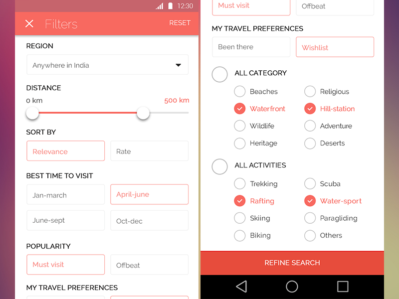
Too often the filtering experience on the web is broken and frustrating, making it just unnecessarily difficult for customers to get to that shiny comfortable range of relevant results. When designing the next filter, take a look at some of the common issues that you might want to avoid, and hopefully avoid all the frustration that comes from broken and inaccessible implementations. Not to say that displaying filters above the results is always better by default. On Asos, every filter input causes jumps to the top of the page, so customers have to manually scroll down to continue filtering.
Unlike sorting, which merely rearranges the results according to some preferred attributes (soft boundaries), filters always represent hard boundaries. Not enough proper filters and users shoot way over the comfortable range; too many filters and users end up with zero-results and abandon the site altogether. While we often think of them appearing when booking flights or shopping online, filters are frequently used in pretty much every interface that features more than a handful of data points. It’s also possible to overlay an animated or static layer to filter images within Kapwing. Find a free filter online or search for a free filter in Kapwing’s stock image library, integrated with Pexels and Unsplash. If you have an overlay filter, drop both layers onto the Kapwing canvas and adjust the opacity of the top layer.
When you need to let the high-frequency components shine while suppressing the low-frequency noise, high-pass filters come to the rescue. Discover the intricacies of high-pass filter design, including critical considerations such as passband edge, stopband attenuation, and transition band width. The cutoff frequency of a low-pass filter determines the point at which the filter begins to attenuate the signal. It is crucial to select the appropriate cutoff frequency based on the desired frequency range to be passed through the filter. The roll-off refers to the rate at which the filter attenuates the signal beyond the cutoff frequency.
Design a Chebyshev Type I filter with the same specifications as the Butterworth filter above. Other MathWorks country sites are not optimized for visits from your location. Filter Designer allows you to generate MATLAB code to re-create your filter. This enables you to embed your design into existing code or automate the creation of your filters in a script.
To save the displayed parameters as the default values, click Save as Default. To restore the MATLAB-defined default values, click Restore Original Defaults. Change the selection in Filter Order to Minimum Order in the Design Region and leave the other parameters as they are. You can change the x- or y-axis units by right-clicking the mouse on an axis label and selecting the desired units.


No comments:
Post a Comment